Japan in Northwest Thailand during World War II
| N 18°32.300 E 99°03.000[1] |
Ban San Khayom[2] Bridge (Th: สะพานบานสันกะยบม / Jp: バンサンカヨム橋) Page 1 of 11 |
Railroad Sta |
| Text | Notes | ||||||||||||||||||||||||||||||||||||||||||||||||||
|
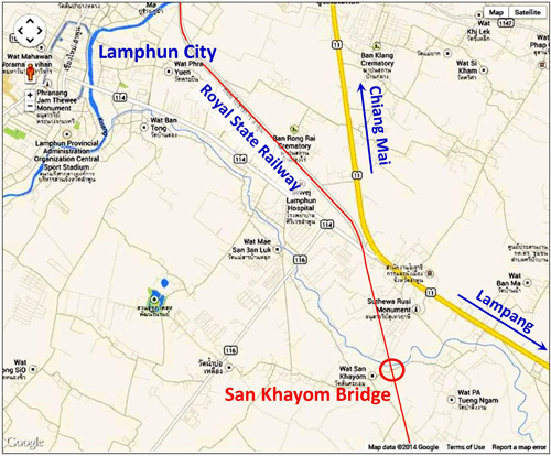
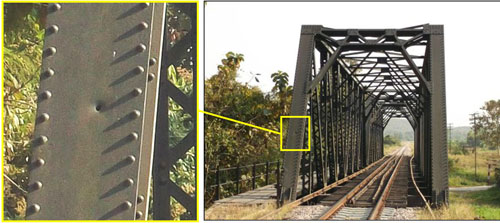
This bridge is noteworthy because it is perhaps the only structure remaining in northwest Thailand that displays damage resulting from probable air attacks during World War 2.[3a] Three distinct holes are visible, along with several other details whose origins are less clear. A subsequent 70 years of field testing have vindicated railway engineering judgment which apparently determined the damage to be not structurally significant. Unfortunately no documentation seems to exist, or at the least to be currently available, regarding the incident(s) that caused the damage. The presentation here varies from others on this website in providing rather greater detail: this in hopes that it may motivate knowledgeable readers to share information. The local map below is current; however, in WW2, Thai Route 11 (shown in yellow) linking Chiang Mai, to the north, through Lamphun with Lampang, to the southeast, did not exist.[4]
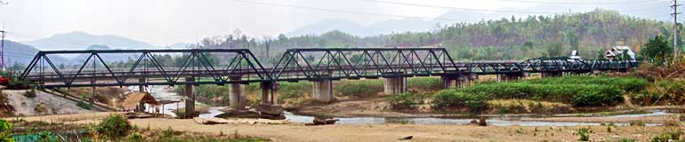
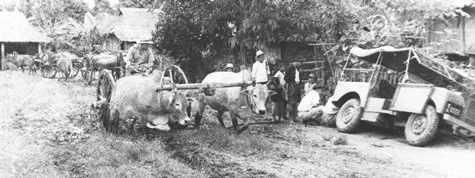
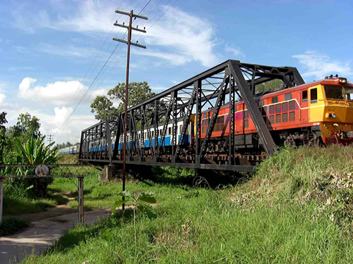
From the photo above, the importance of a rail system to Thailand, prior to the development of a viable road system, should be apparent. One piece in that rail system was the Pratt through-truss railway bridge at Ban San Khayom. It consists of two 40m spans crossing the Nam Mae San (น้ำแม่สาน) (San Creek), about 7 km southeast of Lamphun, on a 3km long straight section of track with a bearing of about 167°/347°. The creek was not navigable:[5]
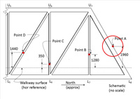
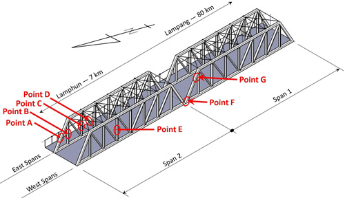
Damage Points
Dates for damage at specific points cannot be determined with information currently available; however, it seems likely that the designated points (except E), were the result of military action, and the only such action in the area was during WW2. A list, admittedly incomplete, of WW2 events that might have included action at the bridge, is included at Recorded Events. Another list, also open-ended, of aircraft with armament, and units using those aircraft, all on record as having operated over northwest Thailand during WW2, is included at Weaponry and platforms. To round out a picture of the immediate area, some period information about the area is available on the Lamphun Airstrip and Wat Phra Yuen webpages.
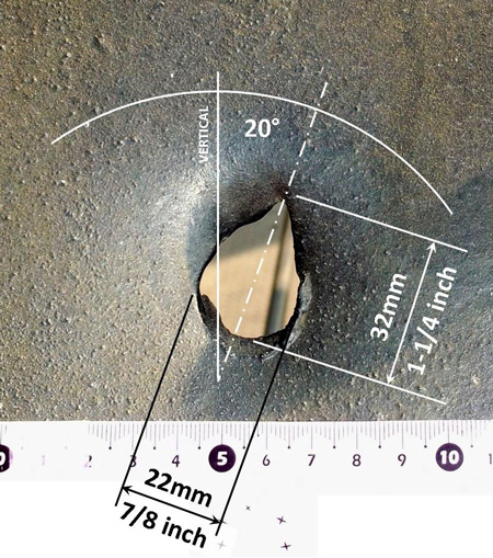
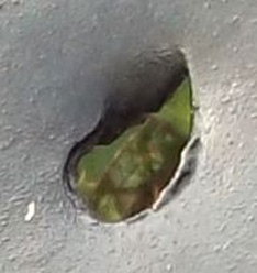
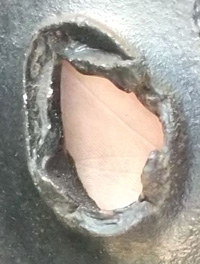
This is the first of three definite shell holes. A projectile fired from north of the bridge passed through a 10mm (3/8 in) structural steel plate in the east leg of the north portal frame of Span 2: [A01] Looking south at the entry point for the hole at Point A; with dimensions added:[A01a]
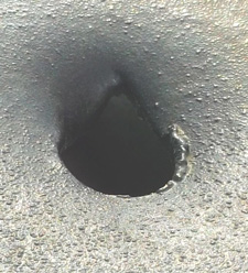
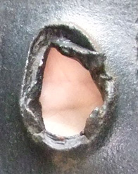
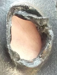
Oblique views of entry point:[A02]
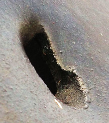
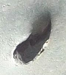
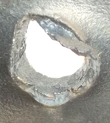
Oblique views of exit point:[A03]
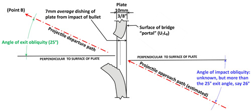
Discussion about the damage at Point A Presented as an isolated ballistic event, a cross-section of Point A, viewed towards the west, looks something like this:[A04]
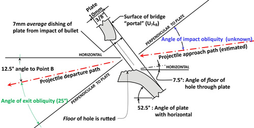
In the sketch, the projectile passed from the lower right to the upper left. The angle of departure, 25°, can be measured by referring to the projectile's next collision point in the bridge, Point B. The angle of impact for Point A is not well defined; however, it must have been greater than the 25° exit angle per a ballistics' rule of thumb: If a bullet impacts a target surface at an angle other than head-on (ie, perpendicular or normal), it will depart the target on an angle closer to the perpendicular to that surface.[A04a] In ballistics, angles are usually measured from that perpendicular, and called obliquity or angles of obliquity.[A04b] As applied to the sketch above, the "angle of impact obliquity" (blue) will be greater than the "angle of exit obliquity" (green). Which is to say, the impact angle will be greater than the 25° exit angle. How much greater is, in this case, an unknown. Indentation or dishing at the edge / perimeter of the hole proper averages 7mm (1/4 in) inward from the exterior face of the plate.[A04b1] Putting the sketch above into context, the plate is actually sloped:[A04c]
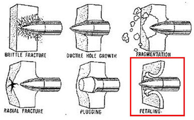
The photos above show the hole to be non-symmetrical around an axis approximately horizontal: the lower half is distinctly circular while the upper half is torn into a point. The shape resembles a tear-drop, with the axes rotated about 20° clockwise off-vertical, as viewed from the impact side of the plate. That rotation may record the direction in which the projectile was pointed off its course at impact, that direction being a function of the bullet's yaw of repose --- the axis shift represents the direction of the yaw of repose, not the angle of yaw of repose itself. The rotation to right of vertical is consistent with right-handed rifling.[A06] The significance of the 7°+ angle of the "floor" of the hole with the horizontal is unclear. If it records the impact angle of the shell, then the shell's path was bent by 12° - 7° = 5° towards a normal to the target plate in going through it. The direction would be consistent with the rule of thumb cited above; however no data has been found by which to judge the magnitude. Observations have been offered that the size of a projectile hole in a steel plate is generally about the same size as the projectile,[A07] or slightly larger.[A07a] There was no weapon during WW2 which used a 22mm caliber projectile. On that basis, the smaller dimension, 22mm (7/8 inch), for the hole at Point A indicates that the projectile was probably of 20mm caliber, which was common during the war.[A07b] The ratio, H/d, (plate thickness (H) vs projectile diameter (d)), is a common factor used in evaluating projectile impacts on targets.[A07c] For Point A, that ratio is 10mm/20mm, or 0.5; which is to say the thickness of the plate was half the projectile diameter. Zukas offers these sketches of "the most common failure modes in impacted plates", among which the most similar to Point A is titled "petaling":[A07d]
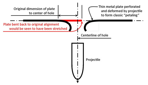
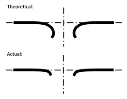
Note that only this one sketch in the group above displays indentation at the impact surface. All the other sketches show formation of a substantial lip at the impact surface. And note that Point A actually does have a very minor "lip", protruding from the impact side, between about "3 o'clock" to "5 o'clock" in the photos looking easterly. The surface at the exit of Point A, however, does not display the "petals" that give "petaling" its name. The reason for this is not clear. The following might be a reasonable explanation. The plate material in the petaling sketch above is portrayed as having been stretched during the projectile's passing through it. Schematically a cross-section might look like the following, similar in appearance to that in the Zukas sketch above, and note the effect of the stretching:[A07e]
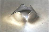
Plate material was apparently lost during formation of Hole A. Thus, a conclusion could be drawn that Hole A does not display classic petaling because some of the material typically forming the petals was lost during the perforation process. Since the target plate was comparatively thick (thicker than in Zukas' sketch), it is possible that the kinetic energy required to pass through the plate generated enough heat to melt the metal and allow it to detach from the target plate. The penetration process might have occurred somewhat like one captured in Werner Mehl's hyperspeed photography of projectile impacts. Stills from a relevant sequence are shown at KURZZEITMESSTECHNIK WERNER MEHL on page 4: there it would appear that some of the molten target material was simply "splashed" away by the violence of the process. In contrast, exit petaling that more closely resembles the Zukas sketch above will be seen in the bridge at Hole G. What Point G offered was a plate that was relatively very thin compared to the projectile diameter: the H/d ratio, 0.18, was much smaller than that at Point A. Note the well defined petaling in the photo below, and how thin the plate is in comparison with the hole diameter:[A07f1]
Applying ballistics jargon, Hole A might be an example of a "thin" plate event, but Hole G, roughly similar in appearance to the above, would be of a "very thin" plate event.[A07f2]
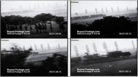
The probable diameter of the shell, 20mm,[A07g] suggests a projectile from a Hispano Suiza HS.404 derivative.[A07h] If the projectile came from an aircraft flying over northwest Thailand during WW2, the 20mm cannon was used on some or all versions of Hawker Hurricanes, Bristol Beaufighters, Lockheed P‑38 Lightnings, and de Havilland Mosquitoes.[A07i] Hurricanes were recorded only once as having been in northwest Thailand, that as escort for a bombing mission over Chiang Mai on 06 March 1942.[A08] Beaufighters were first reported by Shores in Thailand, 14 Mar 1944, (and confirmed by Brown)[A09] and thereafter frequently appeared in the record. P-38s were first recorded by the USAAF Chronology[A10] over northwest Thailand on 23 Apr 1944 and were reported frequently thereafter. Late in the war, an RAF program began to replace Beaufighters with Mosquitoes, but this latter aircraft did not see action over northwest Thailand.[A11] From the above, the maximum potential range of dates for the hole at Point A is March 1942 to August 1945. However, the probable date range lies between March 1944 and August 1945. On this more limited basis, Beaufighters and P-38s are prime candidates. The former had four 20mm auto cannons, nose mounted, usually harmonized at 300 yards.[A12] The latter had one 20mm unit, also nose mounted, for which the strategy was effectively point-and-shoot.[A13] For the latter, the only limitations would have been the pilot's visual acuity plus compensation for bullet drop as the range increased. For a static (or comparatively static) ground target, estimating lead would have been irrelevant for both aircraft. For the accuracy, or lack of it, in aircraft-based gunnery, the Rifleman's Rule was irrelevant. This is generally confirmed in the last sentence of this paragraph from Manual for Fighter Gun Harmonization (emphasis added):[A14] When the firing aircraft is in a dive and the wing tips are parallel to the earth, the drop of the projectile measured at right angles to the extended bore is approximately equal to the drop in level flight multiplied by the cosine of the angle of dive. This change is of such small magnitude up to 30-degree dive that it may be disregarded. Both aircraft would appear to have been quite capable of following these instructions for strafing from the 13th Bomb Squadron:[A15] . . . from a low level approach to the target. . . . At approximately 3,000 yards from the target, the pilot pulls up to 300 ft. above the terrain, spots his target, . . . At approximately 1200 yards from the target, the pilot enters a gentle dive, lines up the target in the sight and commences his strafing run. Firing bursts should be short, starting at 1,000 yards, and breaking off at 400 yards. Gently fan the rudder . . . to effectively cover the target area. . . . Key factors in that description are 1. A starting point at an altitude of 300 feet (100 yards) and at a distance of 1200 yards from a target: if from that starting point, the pilot flew a straight line toward his target, his angle of attack would have been (rounded): arcsin(-100 yards / 1200 yards) = -5° The minus sign indicates the direction is downward, not upward. 2. A breakaway point at 400 yards from the target: at that point, he would have flown through two-thirds of his distance to his target and, hence, two-thirds of his 300 foot starting altitude; so he would have been at 100 feet. Conclusions to be drawn from these instructions are that the following strafing flight characteristics are realistic, especially for combat conditions: 1. An angle of attack as shallow as -5°. With those conclusions, the 7° angle of the floor of the hole might be seen to record the angle of impact as noted above. Dramatic confirmations of the 13th Bomb Squadron's low-altitude strafing tactics lie in gun camera footage available on the Internet. One example: Aerial Dogfights and Strafing, from which the following selection of stills shows a pilot "parting the treetops" to finally arrive about level with a locomotive he's firing on:[A16]
Another tactic in the 13th Bomb Squadron instructions suggests the same source for Hole A could have caused Hole F: during the same firing run: Gently fan the rudder . . . to effectively cover the target area. The rudder movement instruction is confirmed in a Military Channel excerpt: American warplanes strafing enemy trains during World War Two at 04:08-04:19 and again at 04:40-04:59. With the targeted train and its damage, if any, now long gone, that tactic would have so distorted any remaining dispersion pattern that possibly differentiating a P-38 from a Beaufighter would seem now to be impossible (and doing so was always a long shot). Caveat The above scenario can only be hypothetical; but it does establish plausibility for putting a 20mm projectile through Point A at a relatively flat angle from the air.
|
These pages were composed to be viewed best with Google Chrome. See Key for interpreting page content. Revision list. See bottom of Text column on this page. Bibliography supports notes. Please send comments, corrections to author (see Contact Us) Additional information may be found in these forum threads which explored the topic: International Ammunition Association Directions and bearings defined by north-south-east-west (N-S-E-W) nomenclature are approximate. 1.^ Coordinates per Google Earth. 2.^ Names in Thai and English per Royal Thai Survey Department map 4846 III, titled "Lamphun", Series 7018S dated 2007. The Japanese is a simple transliteration. 3.^ The bridge is not listed in Whyte, BR, The Railway Atlas of Thailand, Laos and Cambodia (Bangkok: White Lotus, 2010), p 29. Corrected stationing is as shown per Wisarut Bholsithi posting in Rotfaithai Forum (Engineering Structures) Topic: บันทึกข้อมูลเรื่องสะพาน (Information about Bridges) of 0959 hr 12 Dec 2007. The road passing under the railway bridge is called Maha Bridge Road (per Garmin Nuvi 1250 GPS) which refers to a road bridge about 1.7 km east. 3a.^ Several railway structures in northwest Thailand had been sufficiently damaged to require replacement. Aside from the Chiang Mai railway station, all those structures were south of Lampang. The superficial nature of the damage to this bridge no doubt saved it (Wisarut Bholsithi email of 2224 hrs, 03 Mar 2014). The old Nawarat steel truss road bridge in Chiang Mai also suffered basically "cosmetic" damage that did not require its replacement; however it was demolished in 1966 to make way for the much wider reinforced concrete structure there today (undated conversation with Boonserm Satrabhaya). 4.^ "Terrain" map from Nations Online Project. Annotations by author using Microsoft Publisher. 4a.^ This is a different road, at a later date, but typical of road conditions during WW2: Road between Fang and Tha Ton, 1952. Photograph by Boonserm Satrabhaya, with permission. 5.^ Photo looking NNE at SW corner of bridge by Jack Eisner, circa 2008. Jack Eisner introduced me to the bridge and its shell holes in Dec 2008 when I helped him search out the crash site of Jack Newkirk, a Flying Tiger Ace. The bridge was eventually found not to be related to events preceding Newkirk's death. More recently, the State Railway of Thailand (SRT) has improved the pedestrian walkway cantilevered off the east side of the bridge, which has allowed me and Bob Edgar, a fellow retired engineer, to inspect the bridge more closely. Hence I owe thanks to Jack, to the SRT, and to Bob for their real assistance in this effort. The steel bridge was erected some time prior to the formal opening of the Northern Line on 01 Jan 1922. It replaced an earlier wooden structure erected to connect temporarily to Chiang Mai on 01 May 1920. Delivery from European fabricators for various steel structures on the line had been delayed, probably due to World War I. (per Wisarut Bholsithi email of 2224 hrs 03 Mar 2014). 6.^ The spans are numbered per railway track stationing in this area, ie, increasing towards the north (left in the rendering). Rendering looks southeasterly over northwest corner of bridge; by author using Trimble SketchUp. Annotations with Microsoft Publisher. The view does not conform to the standard of north generally being towards the top of the page because here location of the "holes" dictates the view. 7.^ Recht, RF, and TW Ipson, Final Report: The Dynamics of Terminal Ballistics (Denver: Denver Research Institute, 1962). From its foreword: This report is UNCLASSIFIED when detached from the Appendices which are classified CONFIDENTIAL. That prohibition is still observed, at least on the Internet, as far as I can tell.
Point A:
For truss nomenclature, see Naming convention. A01.^ Both photos extracted from DSCF1824 of 14 Feb 2014. In the following discussion, the bridge steel will be referred to as the "target"; this is for the convenience of discussing the damage to the bridge, which is the only evidence we have about the event. The actual target is assumed to have been a train entering the bridge structure; the train would have been a "target of opportunity", and the damage to the bridge would have been considered "collateral damage". A01a.^ Extract from DSCF1722.jpg of 02 Feb 2014. Annotations done by author with Microsoft Publisher.
A02.^ Left to right, top down, extracts from DSCF2235.jpg (02 May 2014); DSCF2127.jpg and
A03.^ Left to right, top down, extracts from DSCF9214 (02 May 2014) by Grant Wills; DSCF2169 (28 Apr 2014); DSCF2119.jpg and DSCF2117.jpg (19 Apr 2014).
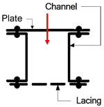
A04.^ Sketch by author using Microsoft Publisher. A04a.^ Rule of thumb: per post#2 by LWD on 04 Mar 2014 in Axis History Forum topic "Aircraft guns and bullet behavior". Confirmed in Rosenberg, Zvi, and Erez Dekel, Terminal Ballistics (Berlin: Springer-Verlag, 2012) Kindle ed, Fig 7.2 (a), 6350+, and preceding text. A04b.^ Most current ballistics literature seems to adhere to this standard, though Rosenberg also uses "inclination angle", the geometric complement to obliquity: ibid, Fig 7.1 (a), 6339, and preceding text. As did Goel, RA, et al, "Behaviour of a Kinetic Energy Projectile on Angular Impact" (Def Sci J 38:3 Jul 1988), p295. A04b1.^ Dishing is subtle, but distinct; lip formation is almost non-existent. With a projectile diameter of 20mm (see below) and a target thickness of 10mm, the ratio of target thickness to projectile diameter, H/d, is 0.5. The resulting cross-section is not consistent with Rosenberg & Dekel, ibid, Fig. 4.7, p 121 (materials and angle of impact do differ). A04c.^ Ibid (sketch revised 04 Apr 2014). The upright portion of the portal frame consists of a built-up section as shown; the red arrow indicates the projectile path into the section:
The projectile missed the lacing straps in exiting the section. (sketch adapted from Bridge Inspector's Reference Manual (Washington: National Highway Institute, 2006) Fig 8.1.6, p 8.1.6, by author using Microsoft Publisher) A05. (deleted). A06.^ A reasonable presentation on yaw is in Ruprecht Nenntiel's How do bullets fly? See sketches in Short ranges and the diagram in The yaw of repose under Long ranges. A07.^ Rule of thumb by LWD, ibid; also DocAV post on International Ammunition Association forum topic "Terminal ballistics", 0550 hrs, 22 Mar 2014; and others. Christopher Perrien by email 0400 03 Apr 2014 clarified that in the case of an oval hole, only the smaller dimension of the hole was meaningful. A07a.^ Tony Williams post of 1206 hrs 14 Apr 2014, in International Ammunition Association Forum. A07b.^ DocAV post of 0550 hrs 22 Mar 2014 on International Ammunition Association Forum advised that the neatness of holes at Points A and F indicated the projectiles were 20mm solid shot, with / without tracer element. A07c.^ Rosenberg, ibid, 2885 (paragraph following equation 4.5b). A07d.^ Zukas, JA (ed), Impact Dynamics (New York: Wiley, 1982), via Synopsis, p 15, in Børvik, Tore, Ballistic Penetration and Perforation of Steel Plates (Trondheim: Fakultet for ingeniørvitenskap og teknologi, 2000).
A07e.^ Sketch by author using Microsoft Publisher.
A07f.^ ibid.
A07f1.^ K. M. Kpenyigba, Tomasz Jankowiak, Alexis Rusinek, Raphaël Pesci, A07f2.^ Rosenberg, ibid, 2885, discussing Thomson analytical model. A07f3.^ LWD commented in email 1931 07 Apr 2014 ". . . [in] multiple plate penetrations . . . typically the projectile hits the second plate with its axis no longer parallel to its line of flight." Military Handbook Survivability, vol 2, Aircraft, Non-nuclear Airframe [MIL-HDBK 336-2] (Washington: DOD, 1983), §5.5.3.1c, p 5‑98: "Impact with shielding often tumbles and distorts the penetrator projectile. . . ." A07f4.^ This is a continuation of a thread from pages 6 and 7. A07g.^ Consensus of replies in Internet forums on various aspects of WWII. A07h.^ Wikipedia Hispano-Suiza HS.404 notes that the gun was licensed to several manufacturers who introduced various modifications. Proper designation for the shell is 20mm x 110mm where the first number is the caliber and the second is the length of the cartridge case, rather than the projectile per Tony Williams' A primer on cartridges. The length of the projectile would appear to be 82-84mm (3.23-3.31 in). This was, for lack of a stated dimension anywhere, scaled from Figs 125 and 127, Ammunition Inspection Guide [TM 9‑1904] (Washington: War Department, 1944), pp 326 and 329. See 20mm projectile length. A07i.^ Culled from "Users" in Wikipedia's Hispano-Suiza HS.404. and sources listed on page 6 under the 20mm holes. A08.^ Shores, Christopher & Brian Cull, with Yasuho Izawa, Bloody Shambles, vol II (London: Grub Street, 2000), pp 288-289. Shores's text does not clearly state that the Hurricanes actually went to Chiang Mai; Dan Ford in his The Flying Tigers doesn't mention that mission which Shore indicates included AVG aircraft. Nor is it clear that the RAF 45 Squadron Blenheims which were to be escorted even reached Chiang Mai that day. It took Neil Frances in Ketchill (Auckland NZ: Publishing Press, 2005), pp 83-84, to confirm that Hurricanes and Blenheims did attack Chiang Mai on 06 Mar 1942. A09.^ Christopher Shores, Air War for Burma (London: Grub Street, 2005), p 180-181. Brown, AS, Silently in the Midst of Things (Victoria BC: Trafford, 2001), p 104. Shores first noted Beaufighter action by 211 Squadron, while Brown wrote of his experiences in 177 Squadron. A10.^ Carter, Kit and Robert Mueller, compilers, Combat Chronology 1941-1945(Washington: Center for Air Force History, 1991), pdf p 364. USAAF 449th Squadron, using P-38s exclusively, is identified as flying missions over Thailand (Jackson, Dan, The Forgotten Squadron (Atglen PA: Schiffer Military History, 2010), pp 51, 93-95, 97, 144, 150). A11.^ 211 Squadron, some other squadrons did fly them in the CBI, but not over northwest Thailand. A12.^ 30 Squadron RAAF Beaufighter Association: Edward Bicknell, Fitter Armourer, but he noted that he could customize aiming the cannon to fit pilot requests. A13.^ Dan Jackson email of 23 Apr 2014. A14.^ Manual for Fighter Gun Harmonization (Washington: Army Air Forces,1945), p 2, para 4b. A15.^ 13th Bomb Squadron website Combat Tactics: Strafing (Area). Instructions were for a Douglas A-26/B-26 Invader, apparently for combat in Korea. The introduction states that the tactics described were "developed through actual combat experience . . . .". The 13th had been in active status continuously (in one form or another) from reactivation in 1929. Combat missions flown from 1942-1944 included the A-26 which was later redesignated the B-26. The instructions for "area" rather than "high-angle" strafing are used here since they better explain how a projectile could produce the relatively flat angle for Hole A. A low level approach is also consistent with pilot experience which had found AA fire limited in northwest Thailand to Chiang Mai and Lampang airstrips plus bridges at Kaeng Luang and Ban Dara (the last two were well south of Lampang). A16.^ Individual frames were frozen with Gom Player, captured with Gadwin PrintScreen, and then enhanced with IrfanView.
| ||||||||||||||||||||||||||||||||||||||||||||||||||
 Looking south at north portal of Span 2