Northwest Thailand during World War II
|
N18°27.325 |
Lampang: Khun Tan Mountain Middle Railway Bridge (Th: สะพานสามหอ / Jp: xxxx) Page 1 of 1 |
Railway Stationing 677+903 [2] |
| Text | Notes | |||||||||||||||||||||||||||||
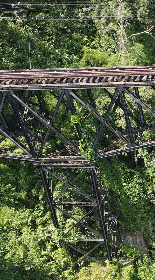
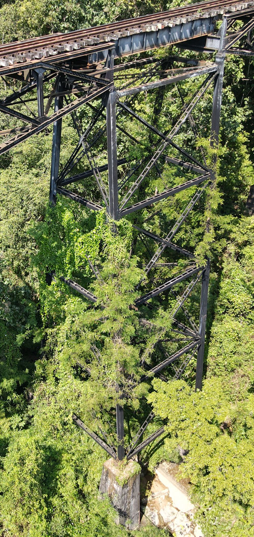
A video of a drone's eye view of the middle bridge of the three major State Railway of Thailand bridges ascending Khun Tan Mountain's eastern slope from the Wang River plain to Khun Tan Tunnel is available here:[2a]
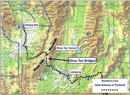
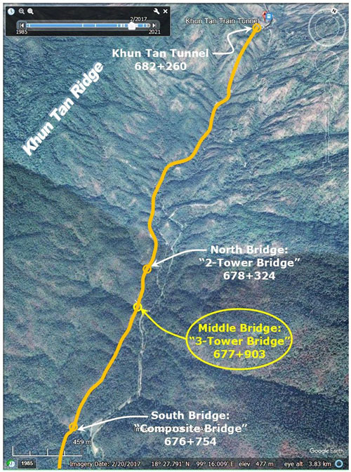
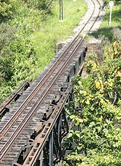
The Middle Bridge, aka, "Pang Yang (S)" or "3-tower bridge", is examined in more detail below. Introduction Khun Tan Mountain provided a substantial obstacle to extending the State Railway of Thailand's Northern Line from Lampang to Chiang Mai. The solution included constructing three major bridges up the mountain's eastern slope:[3]
The three bridges are:[4]
The tan-colored line in the oblique view below traces the Northern Line of the
The three bridges are well described in on-the-ground track-walking by members of ROTFAITHAI.COM. The texts are in Thai, but are fairly well translated if using Google Chrome as a browser. While the links are to relevant portions of their narrations, the first walk (Nakhonlampang) starts at the Composite Bridge and goes north, while the second walk (mirage_II) starts at the Khun Tan Tunnel and goes south:
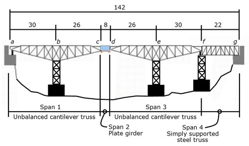
The "3-Tower Bridge" actually has 4-towers Nakhonlampang's explanation (Posts of 12/11/2007 10:12 pm and 12/11/2007 10:16 pm) may be somewhat confusing per Google's translation. Paraphrasing that translation: the structure, two cantilever deck trusses connected with a plate girder, and a simple deck truss extension at the north end, was originally designed to handle 10.5 ton axle loadings and was erected in 1915 with three supporting towers. Viewed from the east (with the mountain as a backdrop as in the drone video), schematically the bridge looked like this:[6]
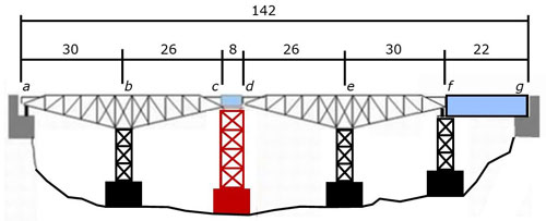
The cantilevered deck spans, 1 and 3, are mirror images, with lengths ab and de four meters longer than lengths bc and de (respectively). Spans 1 and 3 are firmly anchored at points a and f to counteract potential concentrated loading between Points b and e. At point a, steel members are embedded in the concrete abutment (see mirage_II's photo). At point f, the tower would have been designed to handle both the gravity loading of a train and the uplift from a concentrated loading between Points b and e (no photo was found detailing the connections between Truss def, Point f tower, and the foundation for the tower). Single span, cd (in blue), connecting the two cantilever trusses, is a built-up riveted plate girder with web stiffeners presumably pin connected at one end with a roller bearing at the other end, in order to deal with thermal expansion / contraction of the structure from a to f. The single span deck truss fg can be seen in this old photo on rotfaithai. To allow the bridge to handle an increased specification of 15 ton axle loadings, a fourth tower was added in 1967 (as shown in red below at cd), along with considerable supplemental bracing to the original structure, plus the simple deck truss fg was replaced by a welded plate girder (in blue):[7]
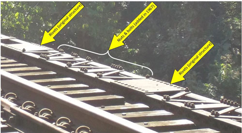
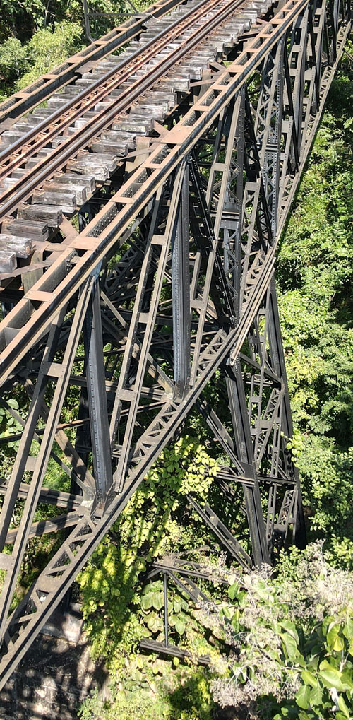
Hence, the so-called "3-tower" bridge now has four towers. If the rotfaithai links above are followed, this is the structure that was examined in 2007 and 2013, some 40+ years after the structure was strengthened. To differentiate old from added structure, there are rules of thumb: one, the original steel structure was riveted throughout, whether shop fabricated or field-erected, while, two, new members and reinforced existing ones were connected with nuts and bolts, and sometimes supplemental members appear to have been shop welded, a process not used in 1915. For examples of a shop-welded built-up member including web stiffeners, see mirage_II's two photos of fg at simple deck truss and end of simple deck truss. Here is an example of diagonal lacing, both original and added to an existing girder:[8]
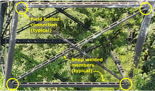
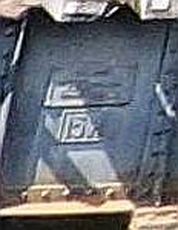
Some simple assemblies were shop fabricated and transported to site. For example, the horizontal members and cross-bracing of the new tower, at cd, appear to have been welded which would have been a shop function. The members were then transported to site and bolted in place:[9]
Other views possibly of interest: South end of bridge (Point a) at abutment:[10]
South (original) tower (Point b):[11]
Added tower (Points c and d):[12]
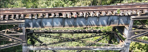
Additional views of the 8-meter span, cd. Not very accessible from the ground, or from the bridge itself, the drone provided these views:[13]
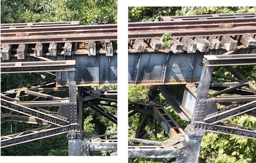
Closeups of end points, c and d:[14]
North (original) Tower (Point e):[17]
Northern-most (original) Tower (Point f) and north abutment (Point g):[18]
|
References are provided in this column for the convenience of the reader. Please advise author of any errors. Readers are encouraged to copy this webpage for their own future reference. See How to Copy Webpages. These pages were composed to be viewed best with Google Chrome. Revision list. See bottom of Text column on this page. Bibliography supports notes. 1.^ Google Earth coordinates 2.^ BR Whyte, The Railway Atlas of Thailand, Laos and Cambodia (Bangkok: White Lotus, 2010), p 28. 2a.^ Link is to YouTube: [Ref: 02370 Lampang\ Railroad\ Khun Tan bridges\ KHUN TRESTLE BRIDGE\ Khun Trestle Bridge Photography 25-10-2022 \Extracts
\ 3.^ Extract from Tactical Pilot Chart TPC J-10C, Burma, Laos, Thailand, Edition 4 (1983). Markup by author using Microsoft Publisher. [Ref: \02370 Lampang\ Railroad\ Khun Tan bridges\ Presentations\ 0 Bridges. grouped\ CNX-LPG RR Map.jpg] 4.^ Table is extracted from Ban San Khayom Bridge, p 7. Stationing, name, span count from BR White, ibid. Coordinates per Google Earth. Photos reference Rotfaithai Gallery collection.
5.^ Google Earth: oblique view (elevation exaggeration = 2) looking approximately north. Markup by author using Microsoft Publisher. [Ref: \02370 Lampang\ Railroad\ Khun Tan bridges \Presentations\ 0 Bridges. grouped\ CNX-LPG RR Map Br 2.jpg]
6.^ Adapted from Nakhonlampang's schematic: Original bridge, by author using Microsoft Publisher.
7.^ Adapted from Nakhonlampang's schematic: Reinforced bridge, by author using Microsoft Publisher.
8.^ Part DSCF2473.jpg of 02 Dec 2014; annotated by author using Microsoft Publisher. Note: this photo is actually of a detail on the North Bridge (Sta 678+324) similar to that on the Middle Bridge. [Ref: \02370 Lampang\ Railroad\ Khun Tan bridges\ Photos-Hak & KhunTan Sta\
9.^ Part of 20221025105818_photo.jpg by Charlie F.O, drone pilot, with markup by author using Microsoft Publisher. [Ref: \02370 Lampang\ Railroad\ Khun Tan bridges\ _pub files\ 2-tower fasteners.jpg]
10.^ Part of 20221025105914_photo.jpg by Charlie F.O, drone pilot. [Ref: \02370 Lampang\ Railroad\Khun Tan bridges\ KHUN TRESTLE BRIDGE\ Khun Trestle Bridge Photography 25-10-2022\ Extracts\D-South abutmt-alt.jpg]
11.^ Part of 2022102511220_photo by Charlie F.O, drone pilot. [Ref: \02370 Lampang\ Railroad\ Khun Tan bridges\ KHUN TRESTLE BRIDGE\ Khun Trestle Bridge Photography 25-10-2022\ Extracts\F-South tower-alt.jpg]
12.^ Part of 2022102511316_photo.jpg by Charlie F.O, drone pilot. [Ref: \02370 Lampang\ Railroad\ Khun Tan bridges\ KHUN TRESTLE BRIDGE\ Khun Trestle Bridge Photography 25-10-2022\ Extracts\G2-mid tower top-obl.jpg]
13.^ Part of 2022102511250_photo.jpg by Charlie F.O, drone pilot. [Ref: \02370 Lampang\ Railroad\ Khun Tan bridges\ KHUN TRESTLE BRIDGE\ Khun Trestle Bridge Photography 25-10-2022\Extracts\ G1-mid tower top.jpg]
14.^ Ibid.
15.^ Nakhonlampang Post 12/11/2007 10:12 pm. 15a.^ Calculation from 16.^ Part of 2022102511250_photo.jpg by Charlie F.O, drone pilot.
17.^ Part of 202210251148_photo.jpg by Charlie F.O, drone pilot. [Ref: \02370 Lampang\ Railroad\ Khun Tan bridges\ KHUN TRESTLE BRIDGE\ Khun Trestle Bridge Photography 25-10-2022\ Extracts\I-North tower.jpg
18.^ Part of 2022102511426_photo by Charlie F.O, drone pilot. [Ref: \02370 Lampang\ Railroad\ Khun Tan bridges\ KHUN TRESTLE BRIDGE\ Khun Trestle Bridge Photography 25-10-2022\ Extracts\H-North abutmt.jpg]
|
|||||||||||||||||||||||||||||